
Designing the 1482, Part 1
By Ken Blaha, former IH Engineer
In this excerpt, former IH Engineer Ken Blaha chronicles the design, development, and production of the 1482 pull-type combine. Blaha’s seven-year career with IH was devoted entirely to 1482 development, from 1974 to 1981. Filled with trials, errors, successes, and lessons, this step-by-step narrative provides a comprehensive view of the creation and perfection of an industry-changing combine.
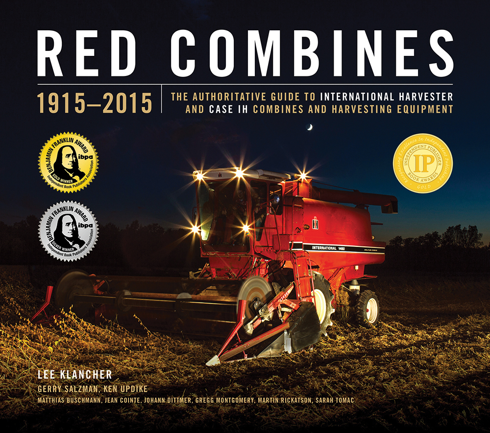
Learn more about the 1482 and all of your favorite IH combines in Red Combines, by Lee Klancher et al.
PART ONE
On this one particular bright, sunny day, I was plowing under corn stubble on our back 40, about a half mile from home. The 806 was really purring that day, easily running third direct. Then I noticed our farm truck waiting for me on the headland. I had no idea what that meant, but soon found out. I had just received a phone call from the assistant chief engineer at the IH East Moline, IL plant, and they wanted to interview me for a job. I returned their call when I got back to the house, and set up an appointment for the next day. I would return home the following day. I couldn't believe the luck, but that was only the start.
My appointment was with Jim Francis, the assistant chief engineer. I don't remember what we talked about anymore, but everything went well. I was offered a design engineer position, and, of course, I accepted. I had lunch with him in the executive dining room and then took a physical. They got me a room for the night and the next morning I came back to pick up a reimbursement check for the expenses of the trip. I was to start work the following Monday, October 14, 1974. Later on, I found out that Jim always bragged about getting me right out of the field to come and work. . . .
It didn't take long until I was given my first project, a variable speed pickup drive for pull-type combines, which at that time meant the 914. The drive was to be based on the variable speed fan drive that was going to be released with the axial flow combines. The fact that it was a mechanical drive using a small electric motor to adjust the variable belt sheaves made it adaptable to a pull-type. The self-propelled machines were using variable speed hydraulic motors for the pickup drive, but the tractors used with pull-types didn't have that capability. My first try on this project failed miserably. We built a test stand and it wouldn't carry the necessary load. I learned the hard way that for a variable belt drive, it made a big difference whether the driver or the driven end had the spring loaded pulley. I redesigned it to reverse the pulleys and then it worked like a champ. I didn't know it at the time, but that was my first job for the experimental CX-38 combine (it became the 1482 in production). The drive never made it onto the 914, but was standard equipment for a pickup equipped 1482.
My next project introduced me to the CX-38. I was assigned to design the main frame. Little did I know what I was getting into. I was soon into the research and planning needed before I could even draw the first line. The first step was to come up with a calculated weight and center of gravity for the main body of the machine. By that time the CX-14 (production 1480) was well along in development, so that gave me data for all the common parts, and there were a lot of common parts. After all, what I was doing was taking the complete threshing, separating, and cleaning system from the 1480 and putting it on two wheels with a tractor pulling it and operating it. At this point I could now make a basic plan view so that I could position the tractor relative to the combine body and header cutting/pickup area. Once this was done, I could position the main axle and then calculate the tongue weight that the tractor would support.
At first glance, calculating the tongue weight looks rather simple. It's not. ASAE (American Society of Agricultural Engineers) has very specific standards on what drawbar load is acceptable based on tractor HP. Due to the size of the CX-38, we were, of course, targeting the largest 2WD or even 4WD tractors to operate this machine. That put us in the high load area, about 2,000 lb. I think, for tongue weight, and we needed it. We wanted weight on the drawbar under all normal operating conditions, but we couldn't exceed the maximum allowed when using the heaviest header with a full grain tank. That meant positioning the axle and then checking all header/grain tank fill combinations. At the time I had to make calculations for either a 12 ft pickup or a 17 ft direct cut header with a full tank of wheat and for a 4 row wide/5 row narrow corn head with a full tank of corn.
The goal was made somewhat easier by the fact that our plans included allowing the tractor to have dual wheels. This meant the tractor had to be far enough forward for the tires to miss the header during a turn. In common sense terms, it gave me a longer lever to lift the front of the combine. However, this wasn't without penalty, and I'll get to that in a moment. I left clearance for a tractor up to 150 inches wide. If I remember correctly, I placed the axle so that by calculation the typical pickup machine ended up with a tongue load in the 750-1000 lb. range, depending on the amount of grain in the tank. The maximum load was not exceeded. Later, I was very pleasantly surprised when the first machine was built and weighed. The tongue weight was 780 lb. with the grain tank empty, but actually went down about 50 lb. with the grain tank full. The result was very stable operation.
Now that the axle was located, the actual design of the frame could start. I designed it based on what was being used for the 914, except, of course, much stronger and heavier. Making room for the large tractors meant that the tongue was pretty long and made from structural rectangular steel tubing with reinforcements added. The 914 had used a two position tongue, transport and operate. Since allowance was made for tractors with duals up to 150 in. wide, another position was added for use with tractors 130 in. or narrower using single tires.
Once the design was complete, it was time to test it. Remember this was before the advent of all the computer analysis that we do now. In fact, the only computer that we had access to was a large main frame located at Hinsdale that we hooked up to by phone. PC's didn't exist yet and hand calculators were just becoming popular. My first calculator cost me $400. Look what kind of computing power you can get for that amount now.
To save money, we enlisted the aid of Hinsdale personnel in building a quarter scale model of the frame out of PVC. All the pieces were made to scale, including material thickness, and were "welded" together with PVC rod that was heated into position just like real welding. Since the real intent of this test was the frame, other parts were added to the model made of wood to support ballasting to simulate, in scale, the real machine with a full grain tank. Lawn mower tires made excellent scale wheels. With the model complete, it was towed over a scale model of our test track with a small lawn tractor. Stresses were checked with a process called stress coat and then were measured with strain gauges. High stress areas were improved and retested. The bottom line is that the original design would have failed our test track run, resulting in major cost to build another frame for test. By use of the model, our first full scale frame was successful with only a couple of minor patches needed. After it completed the test track run, it was used as a test stand for the major parts of the driveline. We had an ASAE paper published that described the plastic model in more detail and quoted the cost and time savings.
During the time that I was designing the main frame, two other engineers were working on other parts of the CX-38, one was designing the driveline and main gearbox, and the other was designing the external sheet metal and the grain tank. As I mentioned earlier, the frame test was turned into a driveline test stand to test the PTO shaft, main gearbox, and rotor drive. It was powered by a DTI-466 engine with a gearbox providing the 1000 RPM PTO output speed. It was mounted on a swinging mechanism that simulated turning corners in the field under load. If I remember correctly, we ran that stand at a constant 120 HP at the rotor with momentary bursts to 180 HP to simulate slugs going through the machine. All in all, a pretty severe test.
The sheet metal designer had two major tasks, the grain tank and a rear deck where the engine would normally be. Both came out very well. The rear deck had a side access ladder and covers over the rotor drive. The grain tank was basically the same as the CX-14 (1480), except the front wall was brought forward into where the cab normally would be. Then a stylish front was added.
Somewhere in the middle of all this there was a change that had a very significant impact on me, the driveline designer resigned and went down the road to work for the green people. Suddenly, I was the driveline designer, too. And the rotor drive that he left me wasn't working. He had tried to use the parts from the self-propelled machines, but they weren't stiff enough, and the result was serious vibration. Now it was time for a new rotor drive pulley support. It took a couple of tries, but I did come up with a new support that worked very well with one exception, it always seemed to run hot for the first 10 hours or so, while it was breaking in. I'm not aware of there ever being any field complaints.
Next up was to try and provide overload protection for the rotor drive. I designed a multiple disk slip clutch set for 1000 ft-lb. Unfortunately, it only worked for a short time. We also tried some off the shelf designs from outside suppliers, but they didn't work any better. We ended up finding out that the drive belt itself provided sufficient protection, and that's what we went to production with.
My next job was unexpected. We had multiple bearing failures in the main gearbox on the test stand. Back to the drawing board. Since the original designer was gone, I recalculated the life for each bearing in the gearbox. The result was that the bearings failed right at about the time they should have. Statistically speaking, this was a very unusual occurrence, and I remember that the first thing that the Timken Bearing representative jokingly said was "what did you do wrong". We were able to come up with some beefier bearings, and we upsized the rotor output shaft at the same time. Problem solved. We did use cooling fans blowing on the gearbox because it was an indoor test, but overheating of the gearbox was never a problem.
The test stand was also used to qualify the telescoping PTO units that connect to the tractor. Our test was absolutely brutal on these parts, and they had to be replaced regularly. 200 hours of operation on this test stand was considered a successful part. The testers greased the U-joints regularly and also measured the temperature of the bearings. The first sign of imminent failure was a rise in temperature, and then the joint wouldn't take grease. At that time, the parts were replaced. Doing this, we didn't have any catastrophic failures. Even with the short expected life, we didn't have any shortage of parts as we were trying to qualify 3 different PTO vendors. Only 2 were successful. . . .
To continue reading, check out Designing the 1482, Part Two.
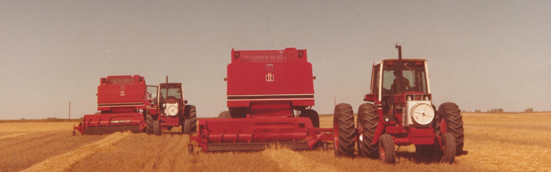
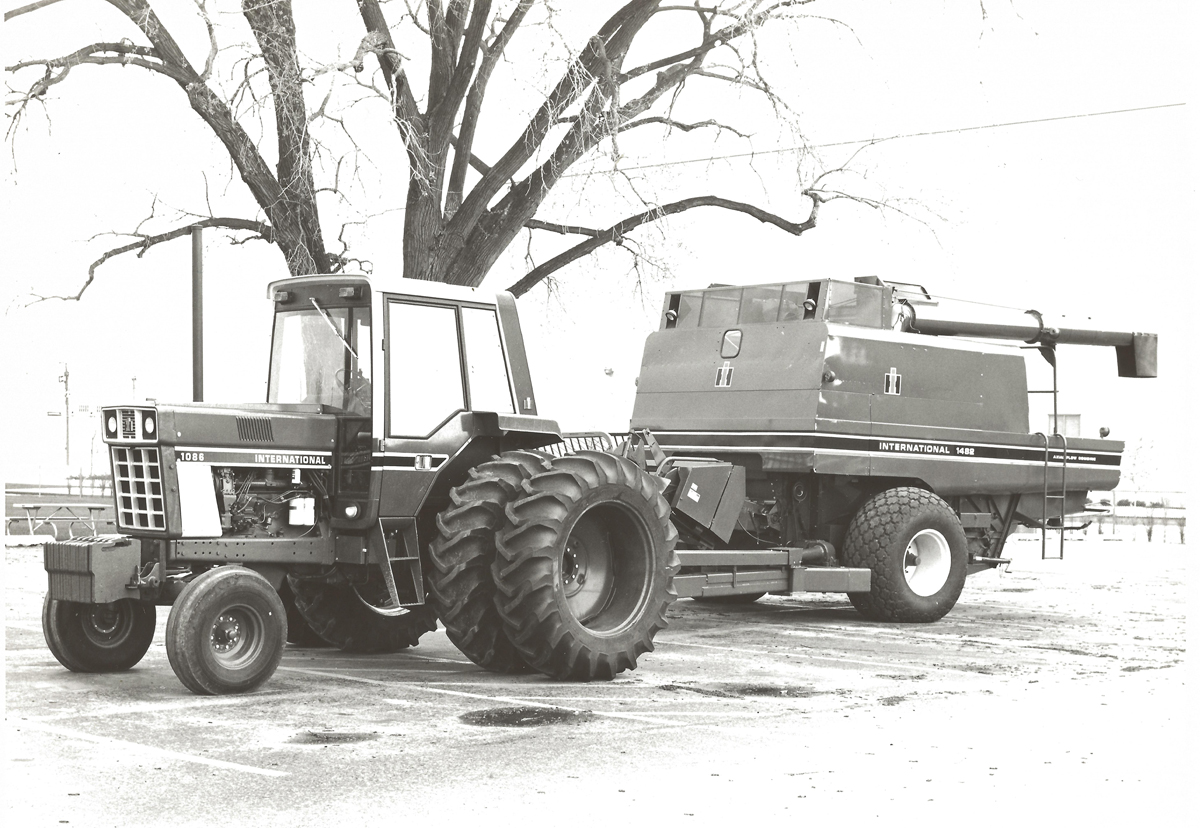
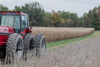
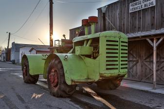
The 1482 was available with a 17.5- or 12.5-foot header or a 132-inch draper pickup. this 1482 pull-type combine is seen behind a 1086 tractor and was photographed in 1979. Wisconsin Historical Society #114838. This image appears in Red Combines by Lee Klancher et al.
-------------------------------
Learn more about all of your favorite IH Combines in Red Combines by Lee Klancher et al.
This article has also appeared in Red Power Magazine in an alternately edited version.
Learn more about the 1482 and all of your favorite IH combines in Red Combines, by Lee Klancher et al.
PART ONE
On this one particular bright, sunny day, I was plowing under corn stubble on our back 40, about a half mile from home. The 806 was really purring that day, easily running third direct. Then I noticed our farm truck waiting for me on the headland. I had no idea what that meant, but soon found out. I had just received a phone call from the assistant chief engineer at the IH East Moline, IL plant, and they wanted to interview me for a job. I returned their call when I got back to the house, and set up an appointment for the next day. I would return home the following day. I couldn't believe the luck, but that was only the start.
My appointment was with Jim Francis, the assistant chief engineer. I don't remember what we talked about anymore, but everything went well. I was offered a design engineer position, and, of course, I accepted. I had lunch with him in the executive dining room and then took a physical. They got me a room for the night and the next morning I came back to pick up a reimbursement check for the expenses of the trip. I was to start work the following Monday, October 14, 1974. Later on, I found out that Jim always bragged about getting me right out of the field to come and work. . . .
It didn't take long until I was given my first project, a variable speed pickup drive for pull-type combines, which at that time meant the 914. The drive was to be based on the variable speed fan drive that was going to be released with the axial flow combines. The fact that it was a mechanical drive using a small electric motor to adjust the variable belt sheaves made it adaptable to a pull-type. The self-propelled machines were using variable speed hydraulic motors for the pickup drive, but the tractors used with pull-types didn't have that capability. My first try on this project failed miserably. We built a test stand and it wouldn't carry the necessary load. I learned the hard way that for a variable belt drive, it made a big difference whether the driver or the driven end had the spring loaded pulley. I redesigned it to reverse the pulleys and then it worked like a champ. I didn't know it at the time, but that was my first job for the experimental CX-38 combine (it became the 1482 in production). The drive never made it onto the 914, but was standard equipment for a pickup equipped 1482.
My next project introduced me to the CX-38. I was assigned to design the main frame. Little did I know what I was getting into. I was soon into the research and planning needed before I could even draw the first line. The first step was to come up with a calculated weight and center of gravity for the main body of the machine. By that time the CX-14 (production 1480) was well along in development, so that gave me data for all the common parts, and there were a lot of common parts. After all, what I was doing was taking the complete threshing, separating, and cleaning system from the 1480 and putting it on two wheels with a tractor pulling it and operating it. At this point I could now make a basic plan view so that I could position the tractor relative to the combine body and header cutting/pickup area. Once this was done, I could position the main axle and then calculate the tongue weight that the tractor would support.
At first glance, calculating the tongue weight looks rather simple. It's not. ASAE (American Society of Agricultural Engineers) has very specific standards on what drawbar load is acceptable based on tractor HP. Due to the size of the CX-38, we were, of course, targeting the largest 2WD or even 4WD tractors to operate this machine. That put us in the high load area, about 2,000 lb. I think, for tongue weight, and we needed it. We wanted weight on the drawbar under all normal operating conditions, but we couldn't exceed the maximum allowed when using the heaviest header with a full grain tank. That meant positioning the axle and then checking all header/grain tank fill combinations. At the time I had to make calculations for either a 12 ft pickup or a 17 ft direct cut header with a full tank of wheat and for a 4 row wide/5 row narrow corn head with a full tank of corn.
The goal was made somewhat easier by the fact that our plans included allowing the tractor to have dual wheels. This meant the tractor had to be far enough forward for the tires to miss the header during a turn. In common sense terms, it gave me a longer lever to lift the front of the combine. However, this wasn't without penalty, and I'll get to that in a moment. I left clearance for a tractor up to 150 inches wide. If I remember correctly, I placed the axle so that by calculation the typical pickup machine ended up with a tongue load in the 750-1000 lb. range, depending on the amount of grain in the tank. The maximum load was not exceeded. Later, I was very pleasantly surprised when the first machine was built and weighed. The tongue weight was 780 lb. with the grain tank empty, but actually went down about 50 lb. with the grain tank full. The result was very stable operation.
Now that the axle was located, the actual design of the frame could start. I designed it based on what was being used for the 914, except, of course, much stronger and heavier. Making room for the large tractors meant that the tongue was pretty long and made from structural rectangular steel tubing with reinforcements added. The 914 had used a two position tongue, transport and operate. Since allowance was made for tractors with duals up to 150 in. wide, another position was added for use with tractors 130 in. or narrower using single tires.
Once the design was complete, it was time to test it. Remember this was before the advent of all the computer analysis that we do now. In fact, the only computer that we had access to was a large main frame located at Hinsdale that we hooked up to by phone. PC's didn't exist yet and hand calculators were just becoming popular. My first calculator cost me $400. Look what kind of computing power you can get for that amount now.
To save money, we enlisted the aid of Hinsdale personnel in building a quarter scale model of the frame out of PVC. All the pieces were made to scale, including material thickness, and were "welded" together with PVC rod that was heated into position just like real welding. Since the real intent of this test was the frame, other parts were added to the model made of wood to support ballasting to simulate, in scale, the real machine with a full grain tank. Lawn mower tires made excellent scale wheels. With the model complete, it was towed over a scale model of our test track with a small lawn tractor. Stresses were checked with a process called stress coat and then were measured with strain gauges. High stress areas were improved and retested. The bottom line is that the original design would have failed our test track run, resulting in major cost to build another frame for test. By use of the model, our first full scale frame was successful with only a couple of minor patches needed. After it completed the test track run, it was used as a test stand for the major parts of the driveline. We had an ASAE paper published that described the plastic model in more detail and quoted the cost and time savings.
During the time that I was designing the main frame, two other engineers were working on other parts of the CX-38, one was designing the driveline and main gearbox, and the other was designing the external sheet metal and the grain tank. As I mentioned earlier, the frame test was turned into a driveline test stand to test the PTO shaft, main gearbox, and rotor drive. It was powered by a DTI-466 engine with a gearbox providing the 1000 RPM PTO output speed. It was mounted on a swinging mechanism that simulated turning corners in the field under load. If I remember correctly, we ran that stand at a constant 120 HP at the rotor with momentary bursts to 180 HP to simulate slugs going through the machine. All in all, a pretty severe test.
The sheet metal designer had two major tasks, the grain tank and a rear deck where the engine would normally be. Both came out very well. The rear deck had a side access ladder and covers over the rotor drive. The grain tank was basically the same as the CX-14 (1480), except the front wall was brought forward into where the cab normally would be. Then a stylish front was added.
Somewhere in the middle of all this there was a change that had a very significant impact on me, the driveline designer resigned and went down the road to work for the green people. Suddenly, I was the driveline designer, too. And the rotor drive that he left me wasn't working. He had tried to use the parts from the self-propelled machines, but they weren't stiff enough, and the result was serious vibration. Now it was time for a new rotor drive pulley support. It took a couple of tries, but I did come up with a new support that worked very well with one exception, it always seemed to run hot for the first 10 hours or so, while it was breaking in. I'm not aware of there ever being any field complaints.
Next up was to try and provide overload protection for the rotor drive. I designed a multiple disk slip clutch set for 1000 ft-lb. Unfortunately, it only worked for a short time. We also tried some off the shelf designs from outside suppliers, but they didn't work any better. We ended up finding out that the drive belt itself provided sufficient protection, and that's what we went to production with.
My next job was unexpected. We had multiple bearing failures in the main gearbox on the test stand. Back to the drawing board. Since the original designer was gone, I recalculated the life for each bearing in the gearbox. The result was that the bearings failed right at about the time they should have. Statistically speaking, this was a very unusual occurrence, and I remember that the first thing that the Timken Bearing representative jokingly said was "what did you do wrong". We were able to come up with some beefier bearings, and we upsized the rotor output shaft at the same time. Problem solved. We did use cooling fans blowing on the gearbox because it was an indoor test, but overheating of the gearbox was never a problem.
The test stand was also used to qualify the telescoping PTO units that connect to the tractor. Our test was absolutely brutal on these parts, and they had to be replaced regularly. 200 hours of operation on this test stand was considered a successful part. The testers greased the U-joints regularly and also measured the temperature of the bearings. The first sign of imminent failure was a rise in temperature, and then the joint wouldn't take grease. At that time, the parts were replaced. Doing this, we didn't have any catastrophic failures. Even with the short expected life, we didn't have any shortage of parts as we were trying to qualify 3 different PTO vendors. Only 2 were successful. . . .
To continue reading, check out Designing the 1482, Part Two.
The 1482 was available with a 17.5- or 12.5-foot header or a 132-inch draper pickup. this 1482 pull-type combine is seen behind a 1086 tractor and was photographed in 1979. Wisconsin Historical Society #114838. This image appears in Red Combines by Lee Klancher et al.
-------------------------------
Learn more about all of your favorite IH Combines in Red Combines by Lee Klancher et al.
This article has also appeared in Red Power Magazine in an alternately edited version.
Related Fuel Posts
Related Books
Red 4WD Tractors